Intro
Color is uniquely human. Uniquely cat. Uniquely dog. If we want to design a camera for dogs, we have to tune it to their perception of light. There isn’t a ground truth of ‘color’ in nature. Color vision for humans is a fraction of the light spectrum, around 380 to 700 nanometers. Other animals can see color higher into the ultraviolet, or down in the infrared. To create a camera for humans, let’s take inspiration from how we view the world—our own eyes. Our eyes don’t have cells sensitive to all photons, rather, our eyes have cells tuned to specific wavelengths of light: cones and rods.
Rod cells are used for night vision, and don’t capture color information, we don’t need to worry about those. Cone cells sense light in long, medium, and short wavelengths along the visual light spectrum. These wavelengths map roughly to Red, Green and Blue color vision. Our eyes capture those individual wavelengths and our brains combine those signals from the different cells into what we perceive as color.
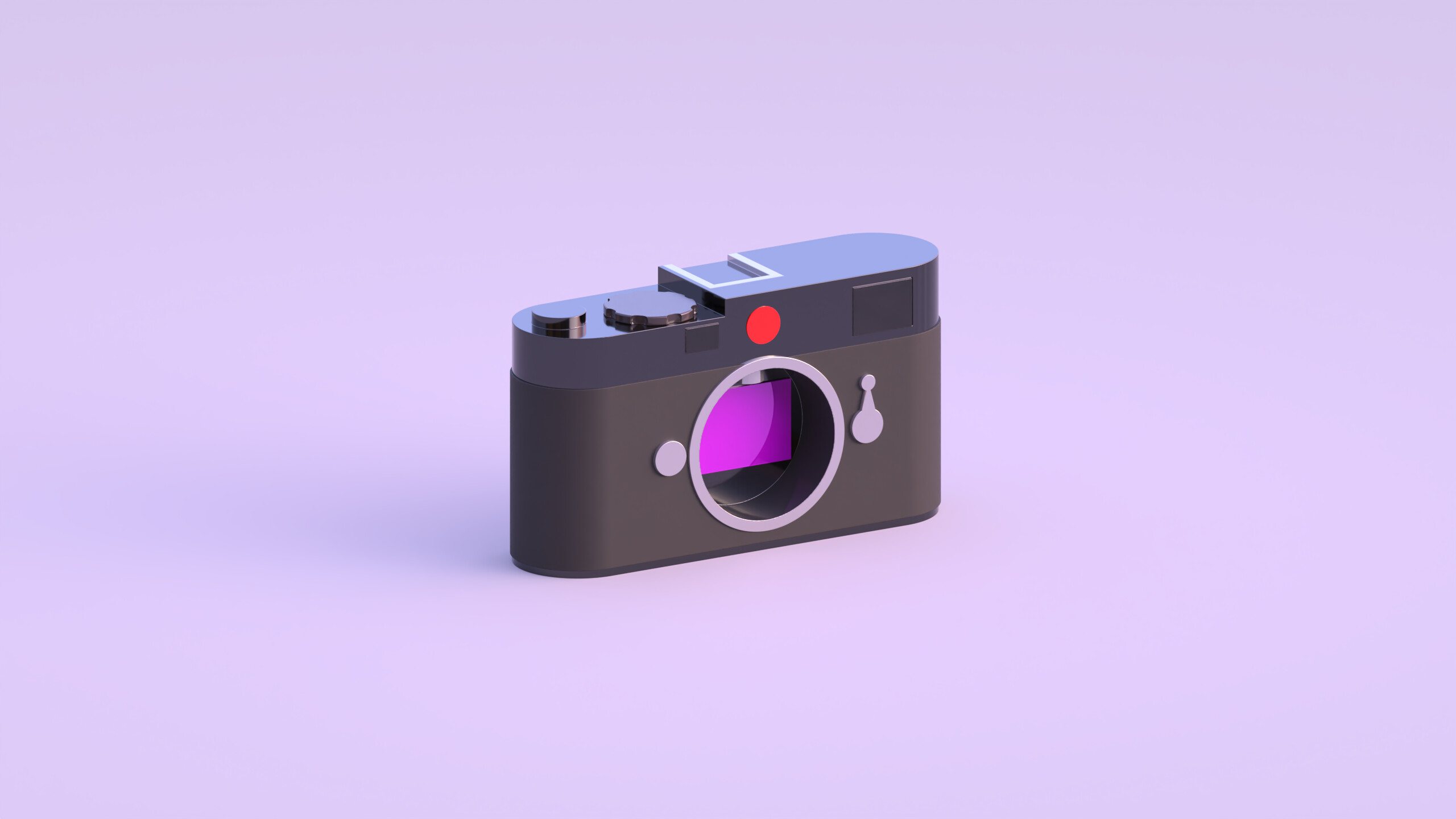
To create a color picture, we need to gather data across multiple wavelengths just like how our eyes work. Then we’ll just overlay those wavelengths over each other and recreate the color! Camera sensors are tuned to capture light within the visible light spectrum. Simple enough, we don’t need to capture X-Rays or Infrared, that wouldn’t match up with how we see the world. Being sensitive to light in the visual portion of the spectrum means we’re only capturing intensity, there’s no way to differentiate colors. So we’re left with a black and white image, only showing luminance (brightness). This is the monochrome sensor we’ll work off of.
The Bayer Color Filter Array
Adding a filter in front of the monochrome sensor limits what wavelengths will make it into our image. Assuming the filter is blue, all light except blue is reflected. The monochrome sensor then captures intensity values at every pixel for how much blue was there in the scene. If we repeat this with red and green filters, we’ll have captured all the color data that we need to create a full color image. Doing this process with black and white film is called the trichrome process
Now, we could definitely do this for color images, but there are some issues:
- We have to carry a bunch of filters around.
- We have to keep the camera and subject completely still.
- We have to take three separate images.
So Trichrome is out. There’s a reason color film was invented. Color film captures all this color information by placing layers of color sensitive film one on top of the other. When taking an image, different layers of film will capture different colors, and when developing the image, all the layers combine to form a color picture1.
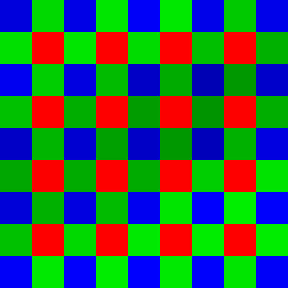
Light sensitive photosites (we’ll call them pixels, but they’re sensing light, not emitting light), aren’t built to let light through the way silver halide crystals can on film. A different approach needs to be taken. By limiting ourselves to just one filter, our pixels are capturing color data, but only for that single color. Since we need three, we have to adjust our approach. Enter the Bayer Color Filter Array, described in this 1975 Patent by Bayer himself.
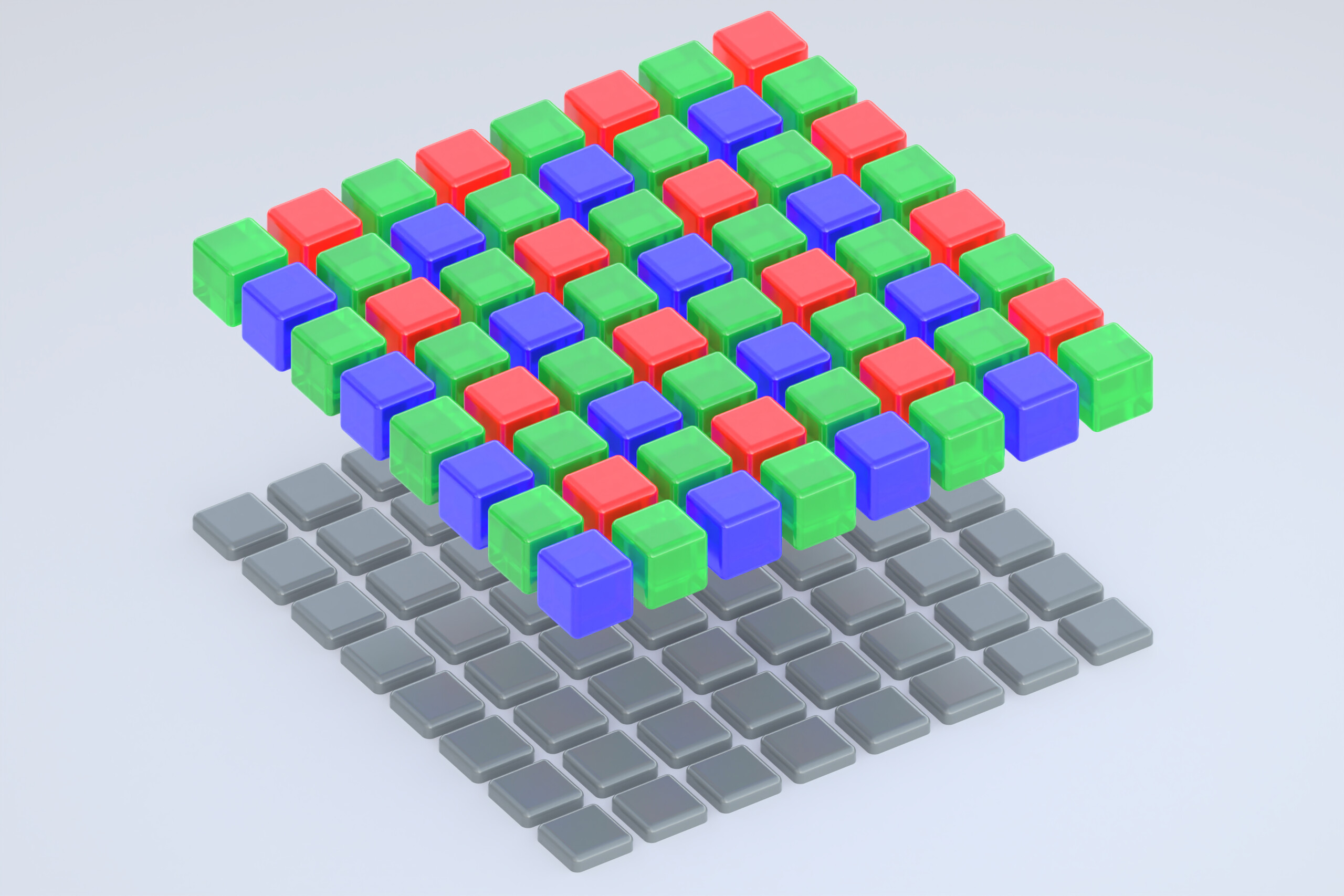
The Bayer Color Filter sits on top of the light gathering sensor
Bayer modeled his Color Filter Array after how our eyes perceive light. Since human eyes are most sensitive to light in the green spectrum, half the pixels on the Bayer Filter are green. The other half of the pixels are sensitive to either Red or Blue light. In the patent, the Green channel is called Luminance and represented with a Y, and the Blue/Red channels are known as Chrominance, represented with a Cb and Cr respectively. This nomenclature comes from the popular Color Space: YCbCr . We’ll stick with the RGB color space for simplicity.
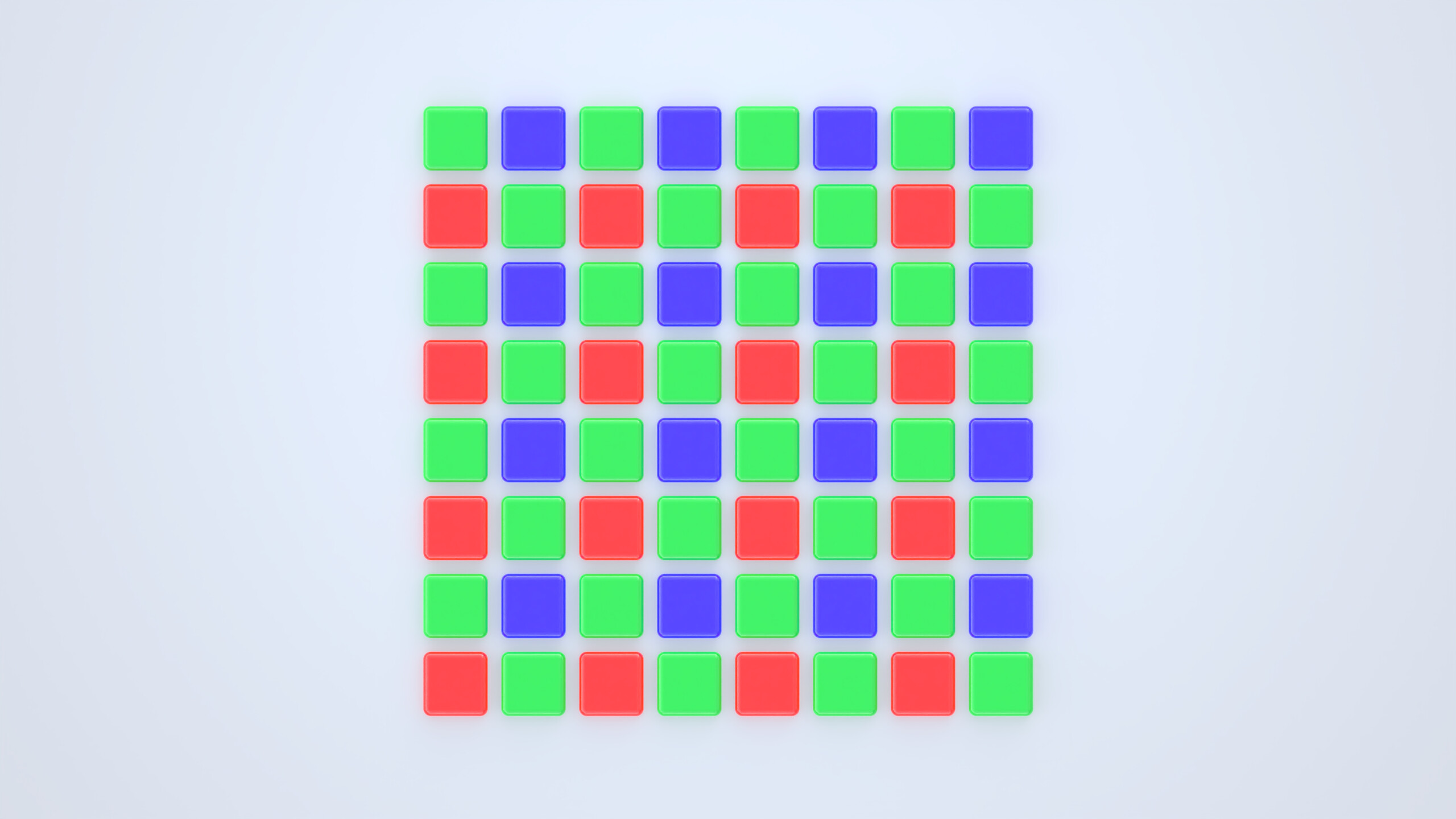
Each pixel under a Bayer Filter captures either Red, Green, or Blue light
With the Bayer Pattern, every pixel on the sensor only gathers light for one of the R, G, or B channels; The pixels miss the other values. In our final image, we want every pixel to have all three values for color. There are two options, binning—combining 4 pixels in the Bayer Pattern, or demosaicing—the process of making an educated guess using neighboring pixels. Binning means you lose half the horizontal and vertical resolution of the image— undesirable to say the least. Demosaicing allows us to keep the original resolution of the sensor while giving us that missing color data.
Demosaicing
Demosaicing algorithms use neighboring pixels (Kernels) around the target pixel to make an educated guess about what the missing color data at a pixel should be. The true color information doesn’t exist—there’s no way of knowing the true value at each pixel. Demosaicing algorithms produce results in practice that are good enough. The simplest algorithm for demosaicing is called Bilinear Interpolation. Bilinear Interpolation looks at the nearest pixels that have the target color we’re trying to calculate and takes the average of those values.
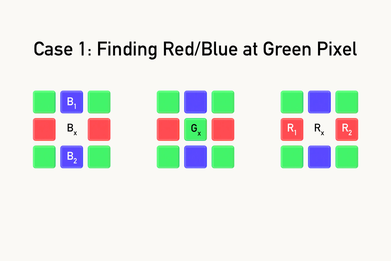
Above, we’re at a green pixel, and we need to figure out what the Blue and Red values should be. So at Bx = (B1 + B2)/2 and Rx = (R1 + R2)/2. Green is a known value at this pixel. We’re just adding the values of B1 and B2 and take the average, and doing the same for R1 and R2.
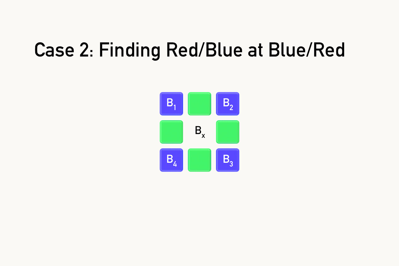
In this example we’re finding the value of blue at a red pixel. We add up the value of all 4 neighboring blue pixels and divide by four to get the average. The math works exactly the same for when we’re at a red pixel and need to guess what the blue value should be.
\[B_x = \frac{B_1 + B_2 + B_3 + B_4}{4}\]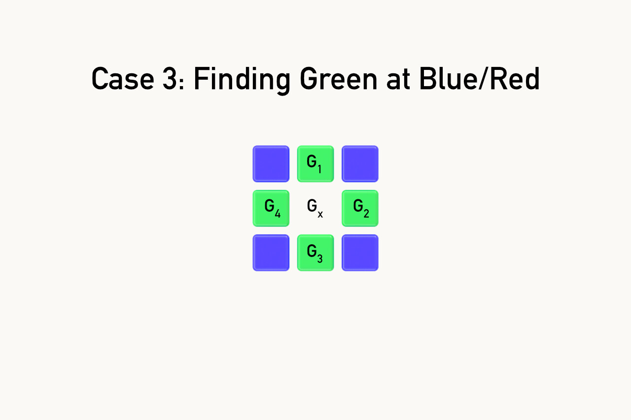 The pixels are arranged slightly differently when trying to find green at a blue or red pixel (Vertical and Horizontal instead of Diagonal), but the math ends up being the same.
Bilinear Interpolation is the naive approach; it doesn’t hold up well when used on real images. Bilinear Interpolation struggles when there are rapid changes in colors, like the edges on high-contrast objects like fences or leaves, where colors change rapidly between rows of pixels. These rapid changes will create artifacts like false color. Imaging Software like Lightroom or Capture One use algorithms with larger kernels, and take into account issues such as sensor noise, dead pixels, edge detection. Demosaicing algorithms aren’t able to perfectly reproduce fine details and some fare better than others. Let’s take a look at what problems demosaicing algorithms face, and compare a few different outputs.
False Color & other artifacts
When demosaicing an image, there are visual artifacts generated as the algorithm attempts to guess what color values belong at each pixel. False color and moire are the most common, appearing in structures and fabrics respectively. With a simple algorithm like bilinear interpolation, high-contrast edges can have drastic changes in values across short distances. These cause False Color to show up in images, presenting as splotches of red/blue/green in areas of high contrast. Moire are those patterns seen where many thin lines next to each other (often intersecting) appear to make new patterns or lines that didn’t exist in the original scene.
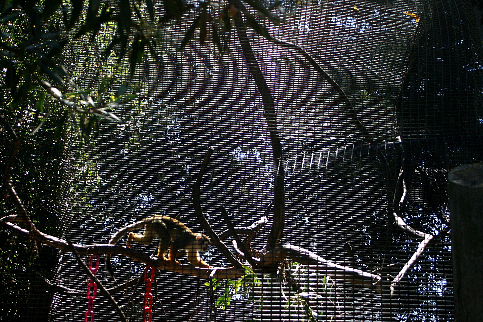
Moire showing up on the cages of the San Francisco Zoo. Image taken from Wikipedia.
Other common artifacts include Zippering, where thin lines can appear to zigzag or zipper down an image because their values fall between rows of pixels. Blurring also happens as a result of both Zippering and False colors, thanks to the rainbowy colors that’ll appear across the edges of objects, lowering perceived contrast and sharpness.
Demosaicing in action
Let’s look at a real example of demosaicing in a picture!
This is a mosaiced portion of the Swiss hillside featured in my iPhone 11 review! Specifically this selection is the roof at the house in the bottom left.
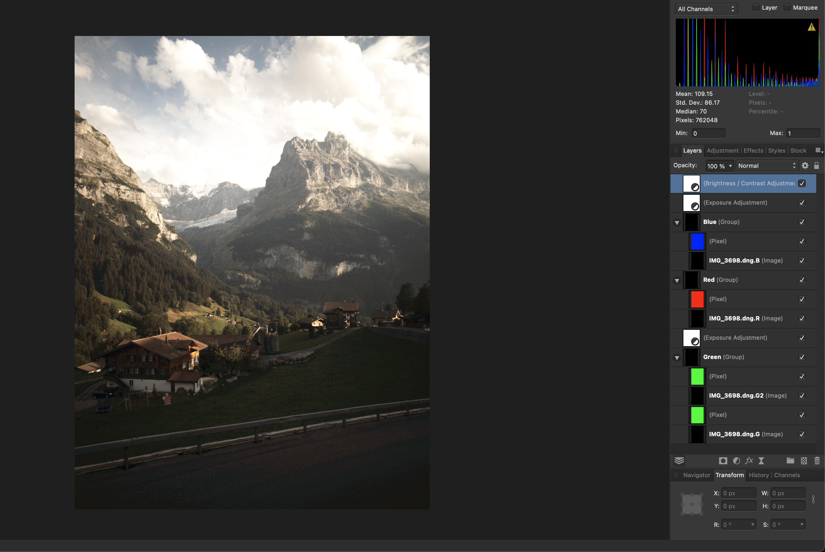
Even without being processed through a demosaicing algorithm, you can already see that it looks similar to what the picture is supposed to be like. At this distance, Affinity Photo (the program being used here), is either blurring the pixels or binning the pixels to show it at this distance. Here I overlayed each layer with the color the sensor assigned to that layer. There’s a G and a G2 layer because of the filter pattern— RGGB. You can combine them in at this point and treat them as one, but they’re technically read by LibRAW as two separate channels. In literature you’ll sometimes see them called Gb and Gr, standing for Green (Blue row) and Green (Red Row). I used the 4channels.cpp to process the RAW image and it spits out all the color channels as separate TIFF files.
Here are the individual red, green and blue channels in the little house. Note that the green channel contains the same amount of pixels as the red and blue combined.
Enough of all these mosaics, let’s actually look at the different results 3 Demosaicing algorithms give when given these pixels.
This is a comparison of 3 demosaicing algorithms. The first is DHT, the second AHD, and the last is Bilinear. DHT is an algorithm designed by Anton Petrusevich (Whose email/website I could not find. I think this is his GitHub) AHD is a default for LibRAW, and Bilinear is the naive approach described earlier. Bilinear has by far the worst output out of the 3. As we move from Bilinear -> AHD -> DHT, you should notice an increase in apparent sharpness and a decrease in random colors. In bilinear, if a contrasting edge falls in a pixel or around a couple pixels, the naive approach of just looking at your nearest neighbors returns a bad result.
Advanced algorithms like DHT use different heuristics when calculating missing color data. Whereas Bilinear determines the value of missing pixels in a single pass, DHT processes images in multiple passes. DHT discovers hot pixels (pixels registering incredibly high or low data compared to their neighbors. Usually a sign that the pixel on the sensor is malfunctioning), has a preference for finding color based on horizontal/vertical pixels instead of diagonal, and calculates green pixels before using that data and calculating the value of missing red and blue pixels.
Edge Cases
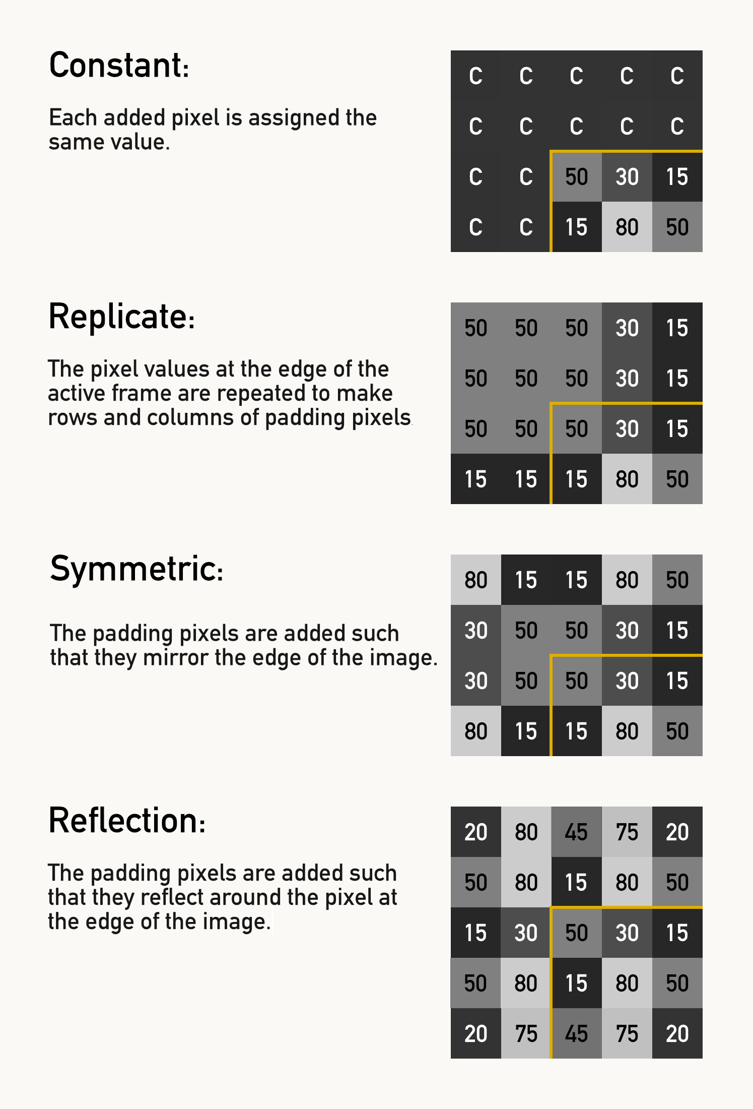
Demosaicing looks at neighboring pixels to work, so what happens on the edges of the sensor? We paid for all those pixels, so we better get to use them. There are a couple of approaches that algorithms can use here, with their own trade offs. This technique is called Edge Padding, since we’re going to pad the edges of the frame with new pixels that we’ll create.
The basic approaches fall into one of these categories:
- None/Crop: Throw those pixels away, only demosaic pixels that have the necessary 3x3 or 5x5 matrix surrounding them.
- Constant: Have the padding pixels have a constant value.
- Replication: Replicate the pixel values at the edge over a couple rows.
- Symmetric: Symmetrically mirror the pixels.
- Reflection: Reflect the pixels across the edge.
Alternatives to the Bayer CFA
The Quad Bayer sensor is an evolution on the regular Bayer sensor, growing in recent popularity due to its advantages when used in smartphones. The Quad Bayer layout is similar to the Bayer, except each pixel on the original Bayer pattern is now 4 pixels on the Quad Bayer. This design has a couple of benefits, like being able to produce high resolution images in good light, while being able to treat binned groups of 4 pixels to act as one larger pixel and demosaic them like in a normal Bayer Filter. Binning combines the signal from 4 separate pixels and using that additional data to improve the signal-to-noise ratio. Quad Bayer filters are why some phones are able to output photos in 48MP during the day in good light, but output 12MP photos when it gets dark. Binning is a bit like using a bucket to catch water. The larger a pixel, the more photons it’s able to collect— like using a bigger bucket to catch rainfall.
Larger pixels capture more photons. The black balls represent photons, the yellow balls represent noise. Assuming the sensor introduces a base level of noise per pixel as part of signal amplification—You’ll get less noise in your images as a result.
Another advantage of Quad Bayer Sensors is their ability to expose 2 pixels within a cluster at a shorter exposure time and the other two at a longer exposure time and use that information to create a Single Shot HDR. Since smaller sensors have worse dynamic range, this single shot HDR can capture a darker and brighter image at the same time, and the image processor on the device can combine the two to create a single high dynamic range image.
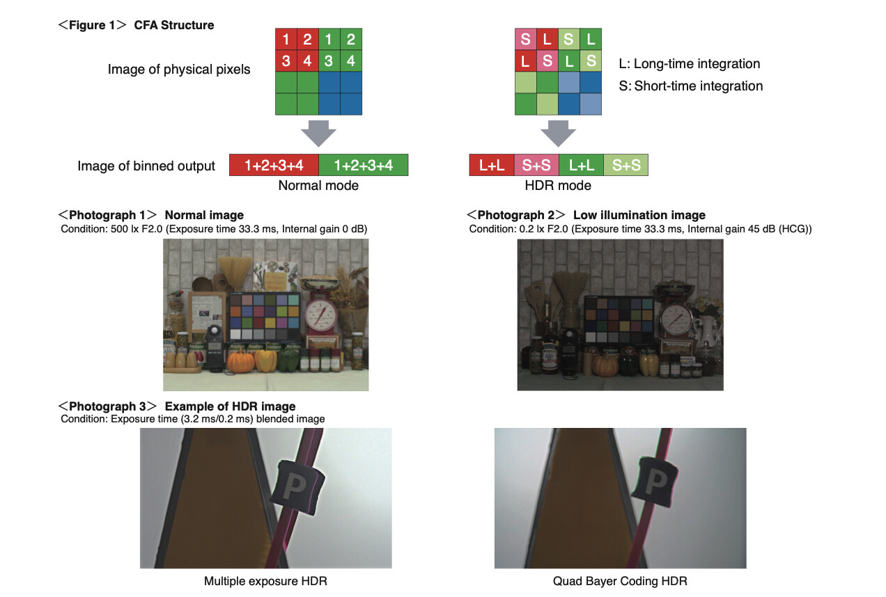
Figure taken from Sony’s IMX294CJK Data Sheet
Another popular Color Filter Array is the X-Trans Sensor, invented by Fujifilm. It has even more green pixels than in Bayer CFAs. By putting Green pixels on every diagonal it claims to “…improve the accuracy of diagonal high-frequency image[s]…” The X-Trans Sensor also has R, G, and B pixels on every row and column to “correctly interpolate colors in high-frequency images”2. Fujifilm claim that the arrangement helps battle against moire in their images, and that they don’t need anti-aliasing filters as a result.
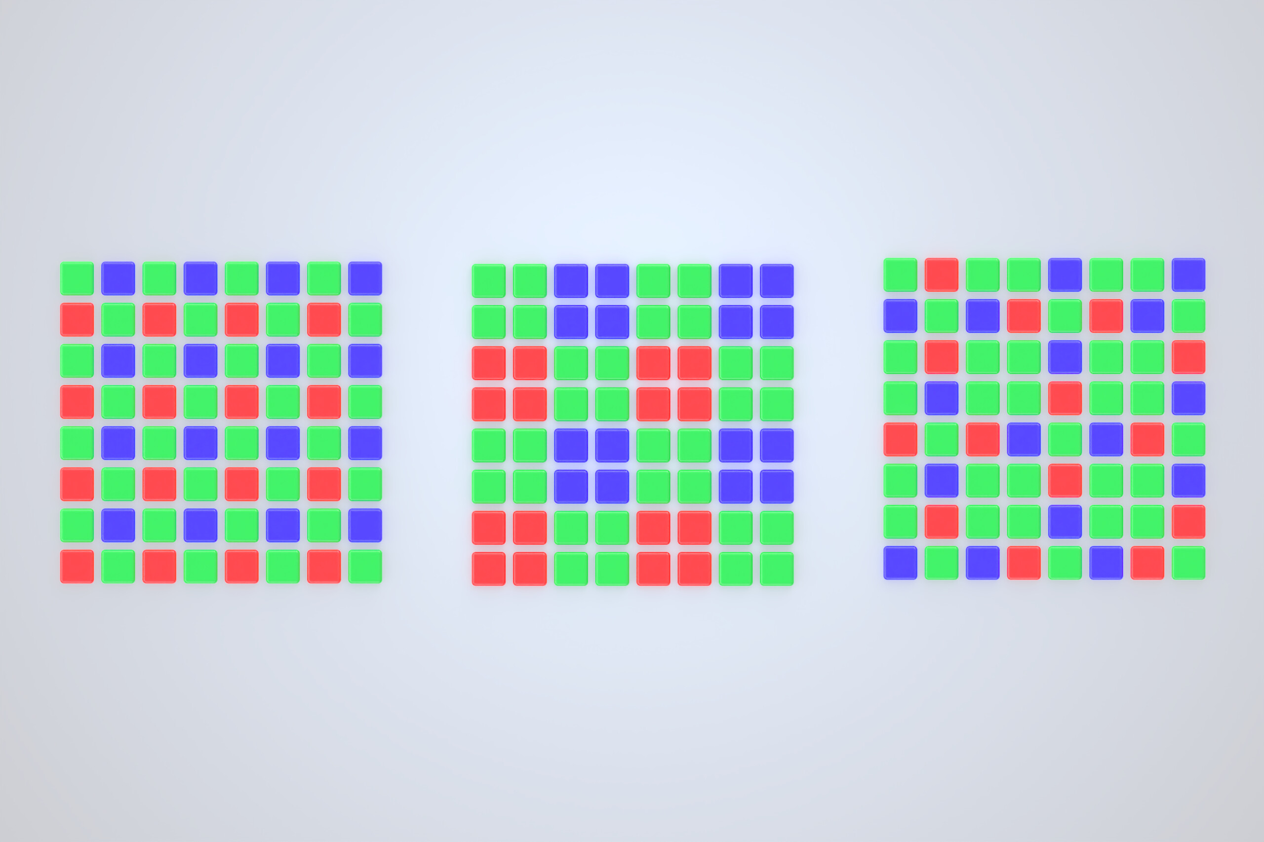
From left to right: A Bayer Sensor, a Quad Bayer, and a X-Trans sensor arrangement
In practice, I don’t think the benefits of X-Trans ever materialized. Fujifilm only uses the sensor type in one line of their cameras (Their APS-C Bodies). The unique sensor arrangement also means image editors can’t use the decades of demosaicing and denoising algorithms specifically designed for Bayer Sensors. Fujifilm is known for their amazing color science on their cameras, but since that same great color science is on their Bayer (GFX Medium Format) cameras as well as their X-Trans sensors, it’s safe to say that it doesn’t have to do with the CFA itself.
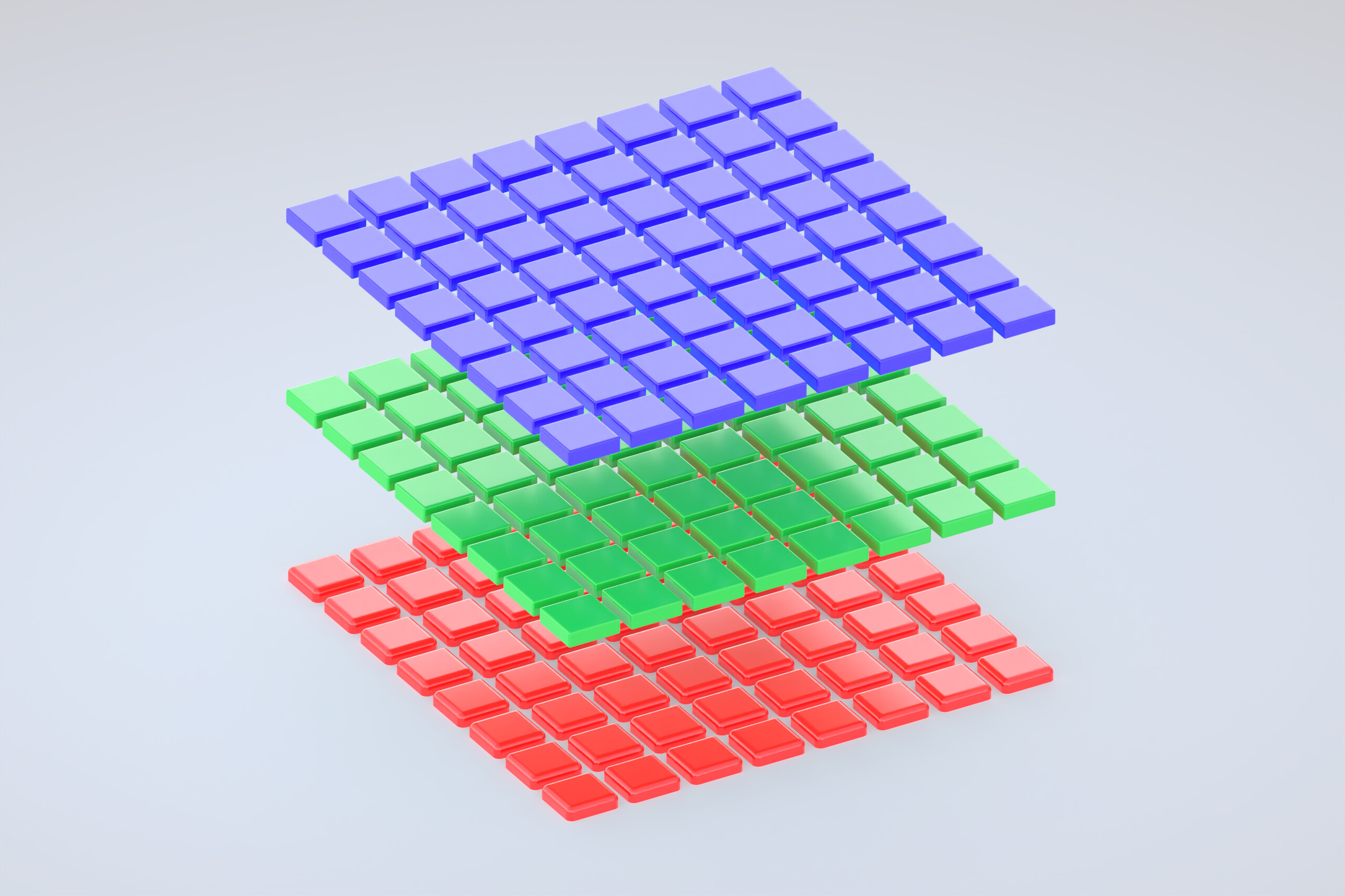
The Foveon Sensor captures RGB values at every pixel. Its poor performance at higher ISOs prevented it from being adopted more widely.
The Foveon sensor is all but dead in 2025, but worth mentioning because its layout is similar to how Color Film captures light. The Foveon Sensor has a Blue layer, Green layer, then a Red layer. With the layers stacked on top of each other, every pixel in the image has true RGB data—No demosaicing required. The downside with Foveon sensors is its issue with high ISO performance. Shooting a Foveon Sensor beyond ISO 100 introduces noise that destroys any benefit of the increased color fidelity at lower ISOs. While Sigma has stated that they’re continuing to invest in the sensor technology, no new cameras have come out with a Foveon Sensor since the Sigma SD Quattro H in 2017.
Capturing True Color
In scientific applications, like taking images of space, accuracy is paramount. A planet or galaxy could be 1 pixel or 4 pixels on an image. Demosaicing and false color artifacts could cause a celestial body to be incorrectly identified. When color accuracy is a requirement, there are some ways of capturing ‘True Color’.
Some cameras with Sensor Shift Technology can move their sensor exactly 1 pixel width side-to-side and up-and-down to capture RGB values for every pixel. The shifting exposes every pixel on the final image to a different pixel in the CFA. The Sensor Shift approach only works for still subjects, limiting its applications to areas like product photography, as any movement will cause color smearing or fuzzy images.3
An antiquated approach is to split the Red, Blue, and Green wavelengths of light using a prism, and directing each of those wavelengths of light into a monochrome sensor (3CCD). This gets you all the color data, but triples the cost of sensors and greatly increases the size of your camera. It’s also possible to stick with one sensor and move 3 sets of filters over the sensor in quick succession to accomplish something similar, but the approach suffers from the same problems as using sensor shift. For consumer cameras, Foveon sensors are the only consumer friendly approach for moving subjects.
So what?
People shoot digicams because it feels crunchy. Old disposables have that grainy, scratchy, faded look. Fujifilm cameras are always sold out because those film simulations are so damn satisfying. It feels good when things are just different from reality. Colors that are close enough are good enough. Algorithms are really good. And no one really cares about accurate colors anyway.
It’s more complicated than this. There are protective layers, anti halation layers. Real life is messy. ↩︎
Camera manufacturers like Lumix stitch distinct images in-camera and produce DNGs that have all the color data. Other manufacturers like Fujifilm require the use of their proprietary software, adding an extra step to the workflow. ↩︎